
еЫЇдљУеѓєи±°
зО∞еЬ®дљ†жЗВеЊЧдЇЖеЬ®3Dз©ЇйЧізЪДдЄАдЇЫеЫЊе±ВеЄГе±АзЪДеЯЇз°АпЉМжИСдїђжЭ•иѓХзЭАеИЫеїЇдЄАдЄ™еЫЇжАБзЪД3Dеѓєи±°пЉИеЃЮйЩЕдЄКжШѓдЄАдЄ™жКАжЬѓдЄКжЙАи∞УзЪДз©ЇжіЮеѓєи±°пЉМдљЖеЃГдї•еЫЇжАБеСИзО∞пЉЙгАВжИСдїђзФ®еЕ≠дЄ™зЛђзЂЛзЪДиІЖеЫЊжЭ•жЮДеїЇдЄАдЄ™зЂЛжЦєдљУзЪДеРДдЄ™йЭҐгАВ
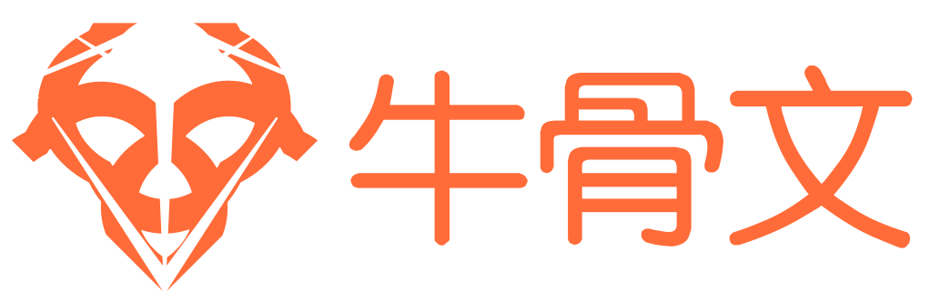
еЬ®ињЩдЄ™дЊЛе≠РдЄ≠пЉМжИСдїђзФ®Interface BuilderжЭ•жЮДеїЇзЂЛжЦєдљУзЪДйЭҐпЉИеЫЊ5.19пЉЙпЉМжИСдїђељУзДґеПѓдї•зФ®дї£з†БжЭ•еЖЩпЉМдљЖжШѓзФ®Interface BuilderзЪДе•ље§ДжШѓеПѓдї•жЦєдЊњзЪДеЬ®жѓПдЄАдЄ™йЭҐдЄКжЈїеК†е≠РиІЖеЫЊгАВиЃ∞дљПињЩдЇЫйЭҐдїЕдїЕжШѓеМЕеРЂиІЖеЫЊеТМжОІдїґзЪДжЩЃйАЪзЪДзФ®жИЈзХМйЭҐеЕГзі†пЉМеЃГдїђеЃМеЕ®жШѓжИСдїђзХМйЭҐдЇ§дЇТзЪДйГ®еИЖпЉМеєґдЄФељУжККеЃГжКШжИРдЄАдЄ™зЂЛжЦєдљУдєЛеРОдєЯдЄНдЉЪжФєеПШињЩдЄ™жАІиі®гАВ
еЫЊ5.19 зФ®Interface BuilderеѓєзЂЛжЦєдљУзЪДеЕ≠дЄ™йЭҐињЫи°МеЄГе±А
ињЩдЇЫйЭҐиІЖеЫЊеєґж≤°жЬЙжФЊзљЃеЬ®дЄїиІЖеЫЊељУдЄ≠пЉМиАМжШѓжЭЊжХ£еЬ∞жОТеИЧеЬ®ж†єnibжЦЗдїґйЗМйЭҐгАВжИСдїђеєґдЄНеЕ≥ењГеЬ®ињЩдЄ™еЃєеЩ®дЄ≠е¶ВдљХжСЖжФЊеЃГдїђзЪДдљНзљЃпЉМеЫ†дЄЇеРОзї≠е∞ЖдЉЪзФ®еЫЊе±ВзЪДtransformеѓєеЃГдїђињЫи°МйЗНжЦ∞еЄГе±АпЉМеєґдЄФзФ®Interface BuilderеЬ®еЃєеЩ®иІЖеЫЊдєЛе§ЦжСЖжФЊдїЦдїђеПѓдї•иЃ©жИСдїђеЃєжШУзЬЛжЄЕж•ЪеЃГдїђзЪДеЖЕеЃєпЉМе¶ВжЮЬжККеЃГдїђдЄАдЄ™еП†зЭАдЄАдЄ™йГље°ЮињЫдЄїиІЖеЫЊпЉМе∞ЖдЉЪеПШеЊЧеЊИйЪЊзЬЛгАВ
жИСдїђжККдЄАдЄ™жЬЙйҐЬиЙ≤зЪДUILabelжФЊзљЃеЬ®иІЖеЫЊеЖЕйГ®пЉМжШѓдЄЇдЇЖжЄЕж•ЪзЪДиЊ®еИЂеЃГдїђдєЛйЧізЪДеЕ≥з≥їпЉМеєґдЄФUIButton襀жФЊзљЃеЬ®зђђдЄЙдЄ™йЭҐиІЖеЫЊйЗМйЭҐпЉМеРОйЭҐдЉЪеБЪзЃАеНХзЪДиІ£йЗКгАВ
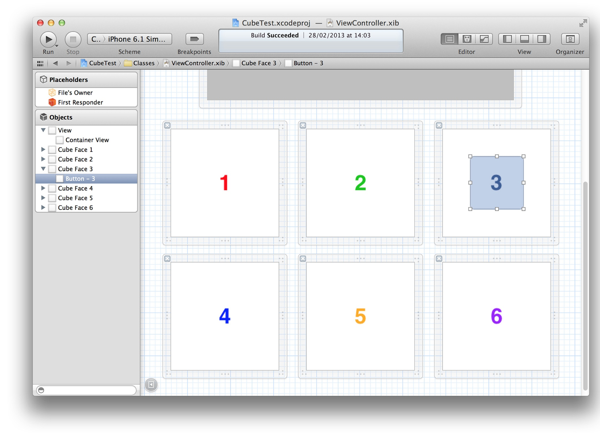
еЕЈдљУжККиІЖеЫЊзїДзїЗжИРзЂЛжЦєдљУзЪДдї£з†БиІБжЄЕеНХ5.9пЉМзїУжЮЬиІБеЫЊ5.20
жЄЕеНХ5.9 еИЫеїЇдЄАдЄ™зЂЛжЦєдљУ
@interface ViewController ()

@property (nonatomic, weak) IBOutlet UIView *containerView;
@property (nonatomic, strong) IBOutletCollection(UIView) NSArray *faces;

@end

@implementation ViewController

- (void)addFace:(NSInteger)index withTransform:(CATransform3D)transform
{
    //get the face view and add it to the container
    UIView *face = self.faces[index];
    [self.containerView addSubview:face];
    //center the face view within the container
    CGSize containerSize = self.containerView.bounds.size;
    face.center = CGPointMake(containerSize.width / 2.0, containerSize.height / 2.0);
    // apply the transform
    face.layer.transform = transform;
}

- (void)viewDidLoad
{
    [super viewDidLoad];
    //set up the container sublayer transform
    CATransform3D perspective = CATransform3DIdentity;
    perspective.m34 = -1.0 / 500.0;
    self.containerView.layer.sublayerTransform = perspective;
    //add cube face 1
    CATransform3D transform = CATransform3DMakeTranslation(0, 0, 100);
    [self addFace:0 withTransform:transform];
    //add cube face 2
    transform = CATransform3DMakeTranslation(100, 0, 0);
    transform = CATransform3DRotate(transform, M_PI_2, 0, 1, 0);
    [self addFace:1 withTransform:transform];
    //add cube face 3
    transform = CATransform3DMakeTranslation(0, -100, 0);
    transform = CATransform3DRotate(transform, M_PI_2, 1, 0, 0);
    [self addFace:2 withTransform:transform];
    //add cube face 4
    transform = CATransform3DMakeTranslation(0, 100, 0);
    transform = CATransform3DRotate(transform, -M_PI_2, 1, 0, 0);
    [self addFace:3 withTransform:transform];
    //add cube face 5
    transform = CATransform3DMakeTranslation(-100, 0, 0);
    transform = CATransform3DRotate(transform, -M_PI_2, 0, 1, 0);
    [self addFace:4 withTransform:transform];
    //add cube face 6
    transform = CATransform3DMakeTranslation(0, 0, -100);
    transform = CATransform3DRotate(transform, M_PI, 0, 1, 0);
    [self addFace:5 withTransform:transform];
}

@end
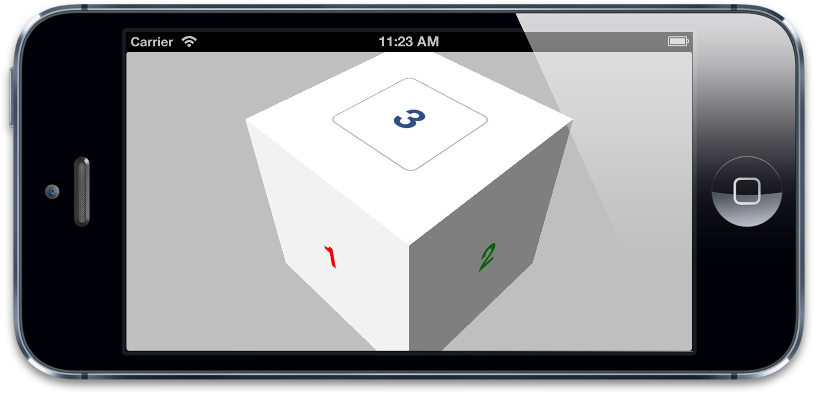
еЫЊ5.20 ж≠£йЭҐжЬЭдЄКзЪДзЂЛжЦєдљУ
дїОињЩдЄ™иІТеЇ¶зЬЛзЂЛжЦєдљУеєґдЄНжШѓеЊИжШОжШЊпЉЫзЬЛиµЈжЭ•еП™жШѓдЄАдЄ™жЦєеЭЧпЉМдЄЇдЇЖжЫіе•љеЬ∞жђ£иµПеЃГпЉМжИСдїђе∞ЖжЫіжНҐдЄАдЄ™дЄНеРМзЪДиІЖиІТгАВ
жЧЛиљђињЩдЄ™зЂЛжЦєдљУе∞ЖдЉЪжШЊеЊЧеЊИзђ®йЗНпЉМеЫ†дЄЇжИСдїђи¶БеНХзЛђеѓєжѓПдЄ™йЭҐеБЪжЧЛиљђгАВеП¶дЄАдЄ™зЃАеНХзЪДжЦєж°ИжШѓйАЪињЗи∞ГжХіеЃєеЩ®иІЖеЫЊзЪДsublayerTransformеОїжЧЛиљђзЕІзЫЄжЬЇгАВ
жЈїеК†е¶ВдЄЛеЗ†и°МеОїжЧЛиљђcontainerViewеЫЊе±ВзЪДperspectiveеПШжНҐзЯ©йШµпЉЪ
perspective = CATransform3DRotate(perspective, -M_PI_4, 1, 0, 0);
perspective = CATransform3DRotate(perspective, -M_PI_4, 0, 1, 0);
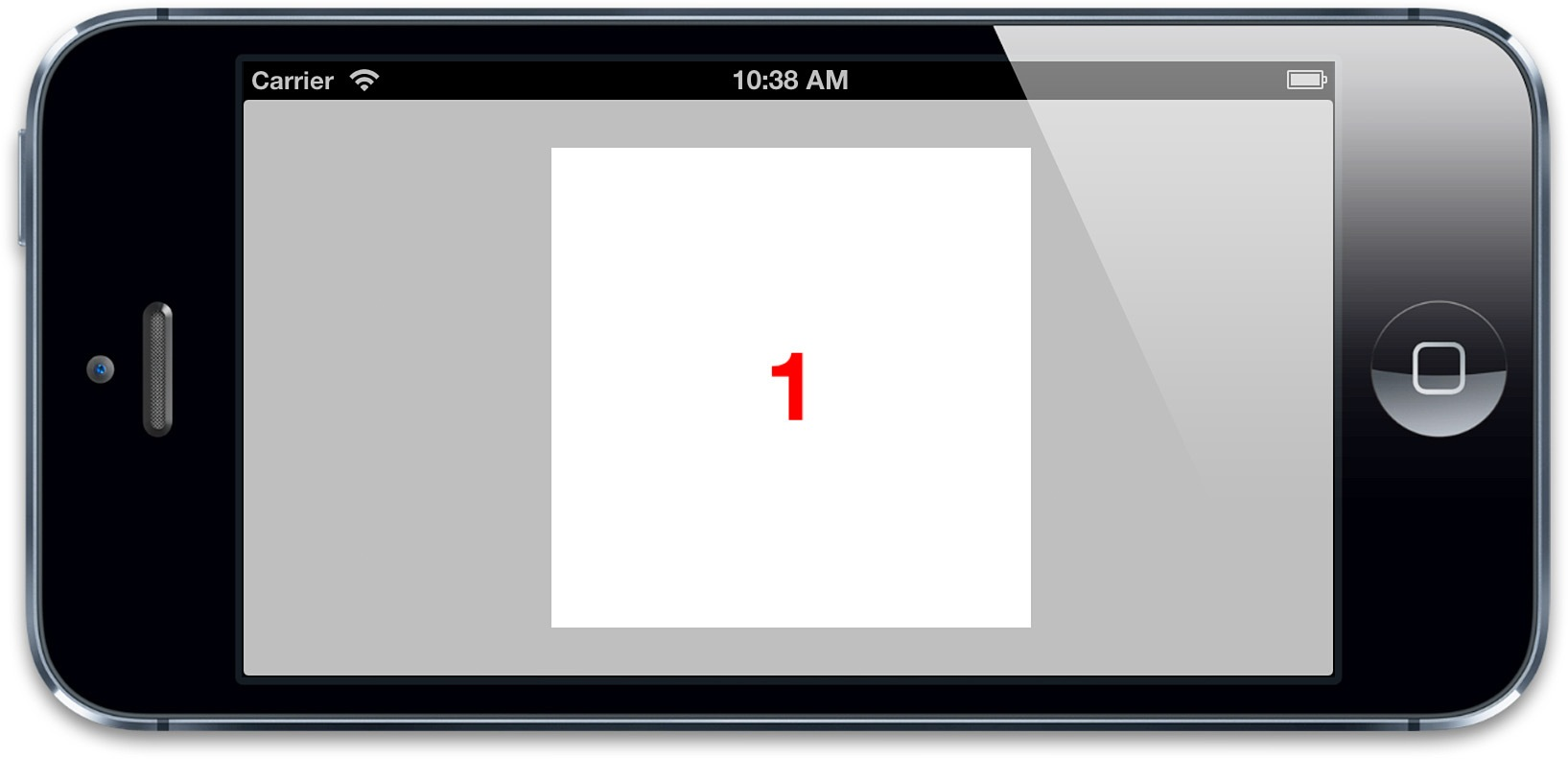
ињЩе∞±еѓєзЫЄжЬЇпЉИжИЦиАЕзЫЄеѓєзЫЄжЬЇзЪДжХідЄ™еЬЇжЩѓпЉМдљ†дєЯеПѓдї•ињЩдєИиЃ§дЄЇпЉЙзїХYиљіжЧЛиљђ45еЇ¶пЉМеєґдЄФзїХXиљіжЧЛиљђ45еЇ¶гАВзО∞еЬ®дїОеП¶дЄАдЄ™иІТеЇ¶еОїиІВеѓЯзЂЛжЦєдљУпЉМе∞±иГљзЬЛеЗЇеЃГзЪДзЬЯеЃЮйЭҐи≤МпЉИеЫЊ5.21пЉЙгАВ
еЫЊ5.21 дїОдЄАдЄ™иЊєиІТиІВеѓЯзЪДзЂЛжЦєдљУ
еЕЙдЇЃеТМйШіељ±
зО∞еЬ®еЃГзЬЛиµЈжЭ•жЫіеГПжШѓдЄАдЄ™зЂЛжЦєдљУж≤°йФЩдЇЖпЉМдљЖжШѓеѓєжѓПдЄ™йЭҐдєЛйЧізЪДињЮжО•ињШжШѓеЊИйЪЊеИЖиЊ®гАВCore AnimationеПѓдї•зФ®3DжШЊз§ЇеЫЊе±ВпЉМдљЖжШѓеЃГеѓєеЕЙзЇњеєґж≤°жЬЙж¶ВењµгАВе¶ВжЮЬжГ≥иЃ©зЂЛжЦєдљУзЬЛиµЈжЭ•жЫіеК†зЬЯеЃЮпЉМйЬАи¶БиЗ™еЈ±еБЪдЄАдЄ™йШіељ±жХИжЮЬгАВдљ†еПѓдї•йАЪињЗжФєеПШжѓПдЄ™йЭҐзЪДиГМжЩѓйҐЬиЙ≤жИЦиАЕзЫіжО•зФ®еЄ¶еЕЙдЇЃжХИжЮЬзЪДеЫЊзЙЗжЭ•и∞ГжХігАВ
е¶ВжЮЬйЬАи¶БеК®жАБеЬ∞еИЫеїЇеЕЙзЇњжХИжЮЬпЉМдљ†еПѓдї•ж†єжНЃжѓПдЄ™иІЖеЫЊзЪДжЦєеРСеЇФзФ®дЄНеРМзЪДalphaеАЉеБЪеЗЇеНКйАПжШОзЪДйШіељ±еЫЊе±ВпЉМдљЖдЄЇдЇЖиЃ°зЃЧйШіељ±еЫЊе±ВзЪДдЄНйАПжШОеЇ¶пЉМдљ†йЬАи¶БеЊЧеИ∞жѓПдЄ™йЭҐзЪДж≠£е§™еРСйЗПпЉИеЮВзЫідЇОи°®йЭҐзЪДеРСйЗПпЉЙпЉМзДґеРОж†єжНЃдЄАдЄ™жГ≥и±°зЪДеЕЙжЇРиЃ°зЃЧеЗЇдЄ§дЄ™еРСйЗПеПЙдєШзїУжЮЬгАВеПЙдєШдї£и°®дЇЖеЕЙжЇРеТМеЫЊе±ВдєЛйЧізЪДиІТеЇ¶пЉМдїОиАМеЖ≥еЃЪдЇЖеЃГжЬЙе§Ъе§Із®ЛеЇ¶дЄКзЪДеЕЙдЇЃгАВ
жЄЕеНХ5.10еЃЮзО∞дЇЖињЩж†ЈдЄАдЄ™зїУжЮЬпЉМжИСдїђзФ®GLKitж°ЖжЮґжЭ•еБЪеРСйЗПзЪДиЃ°зЃЧпЉИдљ†йЬАи¶БеЉХеЕ•GLKitеЇУжЭ•ињРи°Мдї£з†БпЉЙпЉМжѓПдЄ™йЭҐзЪДCATransform3DйÚ襀蚐жНҐжИРGLKMatrix4пЉМзДґеРОйАЪињЗGLKMatrix4GetMatrix3еЗљжХ∞еЊЧеЗЇдЄАдЄ™3√Ч3зЪДжЧЛиљђзЯ©йШµгАВињЩдЄ™жЧЛиљђзЯ©йШµжМЗеЃЪдЇЖеЫЊе±ВзЪДжЦєеРСпЉМзДґеРОеПѓдї•зФ®еЃГжЭ•еЊЧеИ∞ж≠£е§™еРСйЗПзЪДеАЉгАВ
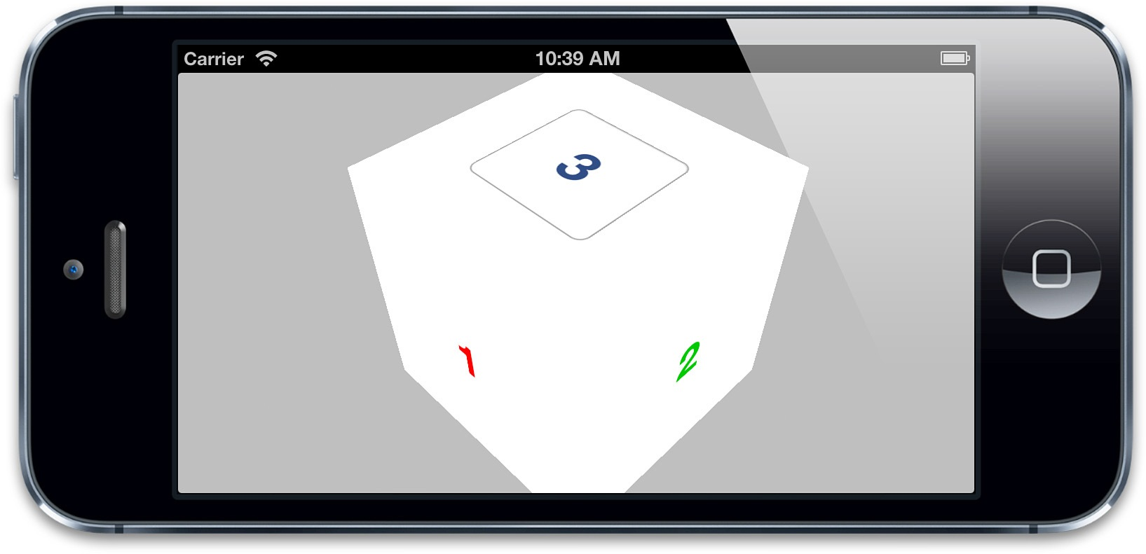
зїУжЮЬе¶ВеЫЊ5.22жЙАз§ЇпЉМиѓХзЭАи∞ГжХіLIGHT_DIRECTIONеТМAMBIENT_LIGHTзЪДеАЉжЭ•еИЗжНҐеЕЙзЇњжХИжЮЬ
жЄЕеНХ5.10 еѓєзЂЛжЦєдљУзЪДи°®йЭҐеЇФзФ®еК®жАБзЪДеЕЙзЇњжХИжЮЬ
#import "ViewController.h"
#import
#import
#define LIGHT_DIRECTION 0, 1, -0.5
#define AMBIENT_LIGHT 0.5
@interface ViewController ()
@property (nonatomic, weak) IBOutlet UIView *containerView;
@property (nonatomic, strong) IBOutletCollection(UIView) NSArray *faces;
@end
@implementation ViewController
- (void)applyLightingToFace:(CALayer *)face
{
//add lighting layer
CALayer *layer = [CALayer layer];
layer.frame = face.bounds;
[face addSublayer:layer];
//convert the face transform to matrix
//(GLKMatrix4 has the same structure as CATransform3D)
//иѓСиАЕж≥®пЉЪGLKMatrix4еТМCATransform3DеЖЕе≠ШзїУжЮДдЄАиЗіпЉМдљЖеЭРж†Зз±їеЮЛжЬЙйХњеЇ¶еМЇеИЂпЉМжЙАдї•зРЖиЃЇдЄКеЇФиѓ•еБЪдЄАжђ°floatеИ∞CGFloatзЪДиљђжНҐпЉМжДЯи∞Ґ[@zihuyishi](https://github.com/zihuyishi)еРМе≠¶~
CATransform3D transform = face.transform;
GLKMatrix4 matrix4 = *(GLKMatrix4 *)&transform;
GLKMatrix3 matrix3 = GLKMatrix4GetMatrix3(matrix4);
//get face normal
GLKVector3 normal = GLKVector3Make(0, 0, 1);
normal = GLKMatrix3MultiplyVector3(matrix3, normal);
normal = GLKVector3Normalize(normal);
//get dot product with light direction
GLKVector3 light = GLKVector3Normalize(GLKVector3Make(LIGHT_DIRECTION));
float dotProduct = GLKVector3DotProduct(light, normal);
//set lighting layer opacity
CGFloat shadow = 1 + dotProduct - AMBIENT_LIGHT;
UIColor *color = [UIColor colorWithWhite:0 alpha:shadow];
layer.backgroundColor = color.CGColor;
}
- (void)addFace:(NSInteger)index withTransform:(CATransform3D)transform
{
//get the face view and add it to the container
UIView *face = self.faces[index];
[self.containerView addSubview:face];
//center the face view within the container
CGSize containerSize = self.containerView.bounds.size;
face.center = CGPointMake(containerSize.width / 2.0, containerSize.height / 2.0);
// apply the transform
face.layer.transform = transform;
//apply lighting
[self applyLightingToFace:face.layer];
}
- (void)viewDidLoad
{
[super viewDidLoad];
//set up the container sublayer transform
CATransform3D perspective = CATransform3DIdentity;
perspective.m34 = -1.0 / 500.0;
perspective = CATransform3DRotate(perspective, -M_PI_4, 1, 0, 0);
perspective = CATransform3DRotate(perspective, -M_PI_4, 0, 1, 0);
self.containerView.layer.sublayerTransform = perspective;
//add cube face 1
CATransform3D transform = CATransform3DMakeTranslation(0, 0, 100);
[self addFace:0 withTransform:transform];
//add cube face 2
transform = CATransform3DMakeTranslation(100, 0, 0);
transform = CATransform3DRotate(transform, M_PI_2, 0, 1, 0);
[self addFace:1 withTransform:transform];
//add cube face 3
transform = CATransform3DMakeTranslation(0, -100, 0);
transform = CATransform3DRotate(transform, M_PI_2, 1, 0, 0);
[self addFace:2 withTransform:transform];
//add cube face 4
transform = CATransform3DMakeTranslation(0, 100, 0);
transform = CATransform3DRotate(transform, -M_PI_2, 1, 0, 0);
[self addFace:3 withTransform:transform];
//add cube face 5
transform = CATransform3DMakeTranslation(-100, 0, 0);
transform = CATransform3DRotate(transform, -M_PI_2, 0, 1, 0);
[self addFace:4 withTransform:transform];
//add cube face 6
transform = CATransform3DMakeTranslation(0, 0, -100);
transform = CATransform3DRotate(transform, M_PI, 0, 1, 0);
[self addFace:5 withTransform:transform];
}
@end
еЫЊ5.22 еК®жАБиЃ°зЃЧеЕЙзЇњжХИжЮЬдєЛеРОзЪДзЂЛжЦєдљУ
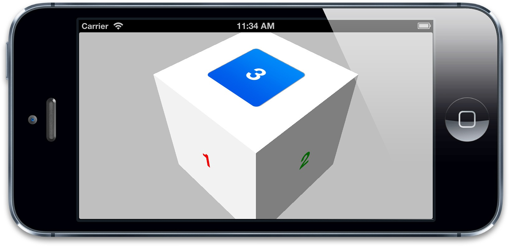
зВєеЗїдЇЛдїґ
дљ†еЇФиѓ•иГљж≥®жДПеИ∞зО∞еЬ®еПѓдї•еЬ®зђђдЄЙдЄ™и°®йЭҐзЪДй°ґйГ®зЬЛиІБжМЙйТЃдЇЖпЉМзВєеЗїеЃГпЉМдїАдєИйГљж≤°еПСзФЯпЉМдЄЇдїАдєИеСҐпЉЯ
ињЩеєґдЄНжШѓеЫ†дЄЇiOSеЬ®3DеЬЇжЩѓдЄЛж≠£з°ЃеЬ∞е§ДзРЖеУНеЇФдЇЛдїґпЉМеЃЮйЩЕдЄКжШѓеПѓдї•еБЪеИ∞зЪДгАВйЧЃйҐШеЬ®дЇОиІЖеЫЊй°ЇеЇПгАВеЬ®зђђдЄЙзЂ†дЄ≠жИСдїђзЃАи¶БжПРеИ∞ињЗпЉМзВєеЗїдЇЛдїґзЪДе§ДзРЖзФ±иІЖеЫЊеЬ®зИґиІЖеЫЊдЄ≠зЪДй°ЇеЇПеЖ≥еЃЪзЪДпЉМеєґдЄНжШѓ3Dз©ЇйЧідЄ≠зЪДZиљій°ЇеЇПгАВељУзїЩзЂЛжЦєдљУжЈїеК†иІЖеЫЊзЪДжЧґеАЩпЉМжИСдїђеЃЮйЩЕдЄКжШѓжМЙзЕІдЄАдЄ™й°ЇеЇПжЈїеК†пЉМжЙАдї•жМЙзЕІиІЖеЫЊ/еЫЊе±Вй°ЇеЇПжЭ•иѓіпЉМ4пЉМ5пЉМ6еЬ®3зЪДеЙНйЭҐгАВ
еН≥дљњжИСдїђзЬЛдЄНиІБ4пЉМ5пЉМ6зЪДи°®йЭҐпЉИеۆ䪯襀1пЉМ2пЉМ3йБЃдљПдЇЖпЉЙпЉМiOSеЬ®дЇЛдїґеУНеЇФдЄКдїНзДґдњЭжМБдєЛеЙНзЪДй°ЇеЇПгАВељУиѓХеЫЊзВєеЗїи°®йЭҐ3дЄКзЪДжМЙйТЃпЉМи°®йЭҐ4пЉМ5пЉМ6жИ™жЦ≠дЇЖзВєеЗїдЇЛдїґпЉИеПЦеЖ≥дЇОзВєеЗїзЪДдљНзљЃпЉЙпЉМињЩе∞±еТМжЩЃйАЪзЪД2DеЄГе±АеЬ®жМЙйТЃдЄКи¶ЖзЫЦзЙ©дљУдЄАж†ЈгАВ
дљ†дєЯиЃЄиЃ§дЄЇжККdoubleSidedиЃЊзљЃжИРNOеПѓдї•иІ£еЖ≥ињЩдЄ™йЧЃйҐШпЉМеЫ†дЄЇеЃГдЄНеЖНжЄ≤жЯУиІЖеЫЊеРОйЭҐзЪДеЖЕеЃєпЉМдљЖеЃЮйЩЕдЄКеєґдЄНиµЈдљЬзФ®гАВеЫ†дЄЇиГМеѓєзЫЄжЬЇиАМйЪРиЧПзЪДиІЖеЫЊдїНзДґдЉЪеУНеЇФзВєеЗїдЇЛдїґпЉИињЩеТМйАЪињЗиЃЊзљЃhiddenе±ЮжАІжИЦиАЕиЃЊзљЃalphaдЄЇ0иАМйЪРиЧПзЪДиІЖеЫЊдЄНеРМпЉМйВ£дЄ§зІНжЦєеЉПе∞ЖдЄНдЉЪеУНеЇФдЇЛдїґпЉЙгАВжЙАдї•еН≥дљњз¶Бж≠ҐдЇЖеПМйЭҐжЄ≤жЯУдїНзДґдЄНиГљиІ£еЖ≥ињЩдЄ™йЧЃйҐШпЉИиЩљзДґзФ±дЇОжАІиГљйЧЃйҐШпЉМињШжШѓйЬАи¶БжККеЃГиЃЊзљЃжИРNOпЉЙгАВ
ињЩйЗМжЬЙеЗ†зІНж≠£з°ЃзЪДжЦєж°ИпЉЪжККйЩ§дЇЖи°®йЭҐ3зЪДеЕґдїЦиІЖеЫЊuserInteractionEnabledе±ЮжАІйГљиЃЊзљЃжИРNOжЭ•з¶Бж≠ҐдЇЛдїґдЉ†йАТгАВжИЦиАЕзЃАеНХйАЪињЗдї£з†БжККиІЖеЫЊ3и¶ЖзЫЦеЬ®иІЖеЫЊ6дЄКгАВжЧ†иЃЇжАОж†ЈйГљеПѓдї•зВєеЗїжМЙйТЃдЇЖпЉИеЫЊ5.23пЉЙгАВ
еЫЊ5.23 иГМжЩѓиІЖеЫЊдЄНеЖНйШїзҐНжМЙйТЃпЉМжИСдїђеПѓдї•зВєеЗїеЃГдЇЖ